

Designing for Permanent Mold: Wall Thickness, Draft, and Radii
A permanent mold die does not forgive the way a sand mold does. Sand gives a little; steel does not. The design rules below are the ones that keep a die filling cleanly, releasing cleanly, and lasting its full life. None of them are exotic. Most parts that cast well in sand need only small adjustments to cast well in permanent mold, and the time to make them is before the die is cut.
Wall thickness
Protocast’s typical minimum wall for permanent mold castings is 0.125 inch, with exceptions possible depending on geometry. The number matters less than uniformity. Aluminum shrinks as it solidifies, and a thick section next to a thin one solidifies last, pulling metal from the thin section and leaving shrinkage porosity at the junction. Where a heavy boss or flange is unavoidable, the gating and riser design feeds it, and if the part needs thin walls in a large area, low pressure fills them more reliably than gravity.
- Blend thick to thin gradually rather than stepping.
- Core out heavy sections where the part allows it; a ribbed pocket is stronger and sounder than a solid block.
- Ribs should be thinner than the wall they attach to, typically 60 to 80 percent, so they do not create a hot spot at the root.
Draft
Draft is the taper on any surface parallel to the direction the die opens or a core pulls. Without it the casting grips the steel as it shrinks and either sticks or drags and tears. A working starting point is 2 degrees on outside walls, with more on inside walls and deep cored features, because the casting shrinks onto internal steel rather than away from it. Shallow features can get by with less; deep, narrow pockets need more. The DFM review will flag any face that needs it.
Radii and fillets
Sharp inside corners do two bad things. In the casting they concentrate stress and can crack during solidification or in service. In the die they create a sharp steel edge that heat-checks first and shortens tool life. Put a fillet on every inside corner. A minimum of about 1/32 inch is common practice; larger is better wherever the design allows, and outside corners benefit from a small radius as well.
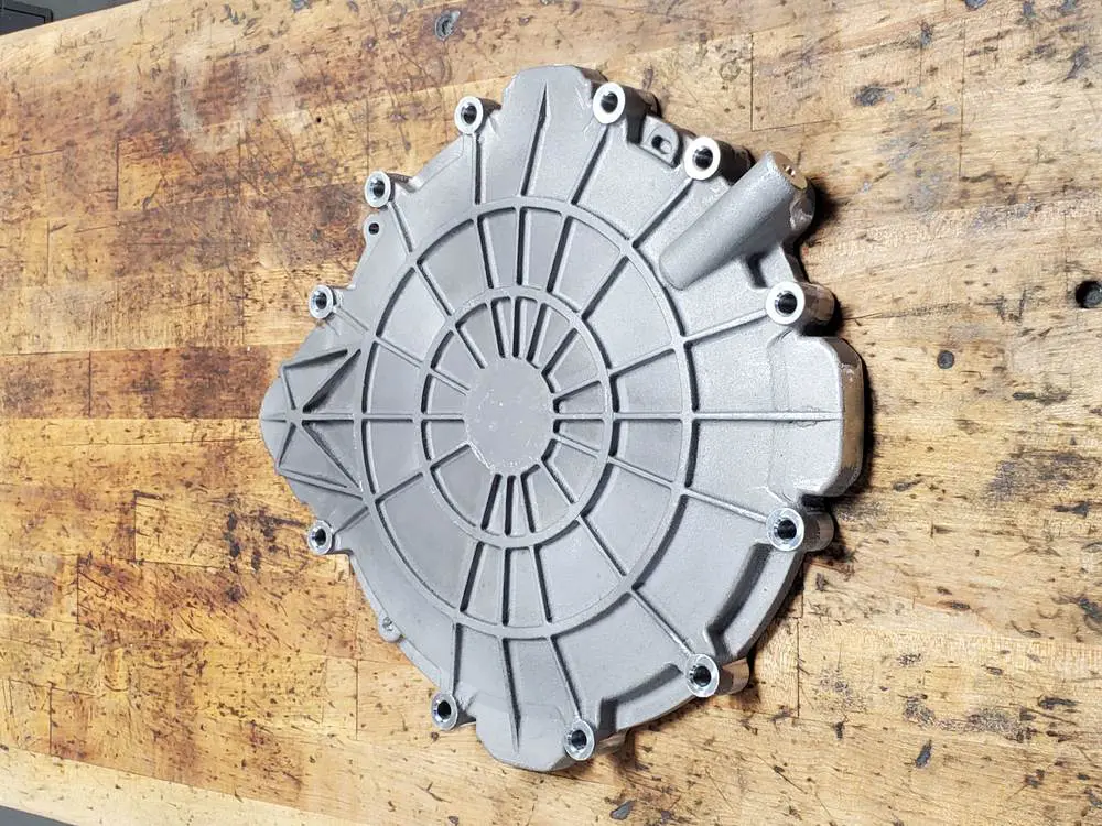
Uniform walls, generous radii, and draft on every vertical face. This housing was designed for the die.
Parting line and cores
Every permanent mold has a parting line where the die halves meet. Placing it thoughtfully simplifies the die, reduces flash, and keeps critical dimensions on one side of the line, where tolerances are tighter. Holes and pockets that pull straight with the die or with a slide can be steel cores. Passages that curve, undercut, or intersect need sand cores, which is semi-permanent mold. Both work; the choice affects cost and cycle time, and it is best made with the foundry.
Tolerances and machining stock
Protocast follows the Aluminum Association Standards for Aluminum Sand and Permanent Mold Castings. As a general guide, dimensions on the same side of the parting line hold tighter than dimensions across it, and tolerance grows with the length of the dimension. Permanent mold sits between sand and high pressure die casting: tighter than sand, wider than die casting, partly because gates and risers are removed by hand on a band saw and die grinder rather than in an automated trim die. A drawing that asks for plus or minus 0.010 inch across a whole casting is asking for something the standards do not support in permanent mold; plus or minus 0.030 is realistic as cast, and anything tighter is machined. Where a feature needs to be tighter than the as-cast tolerance, leave machining stock and machine it. A typical allowance is in the range of 0.045 to 0.060 inch per surface for small parts, more for large ones. Protocast machines its own castings, so the stock is planned with the fixture in mind.
| Feature | Starting point for permanent mold |
|---|---|
| Minimum wall | About 0.125 inch; uniform walls matter more than the minimum |
| Draft, outside walls | About 2 degrees; less on shallow features |
| Draft, inside walls and cores | More than outside walls, increasing with depth |
| Inside corner radius | 1/32 inch minimum; larger wherever possible |
| Rib thickness | 60 to 80 percent of the adjoining wall |
| Machining stock | Roughly 0.045 to 0.060 inch per surface on small parts |
| Surface finish, as cast | 125 to 250 rms |
Typical starting points. The DFM review on your quote replaces every one of these with a number for your part.
Bosses, ribs, and holes
Bosses are the most common source of shrinkage in a permanent mold part, because they are the heaviest section and they sit at the end of the metal path. Keep them as short as the fastener allows, blend them into the wall with a generous fillet, and where a boss must be tall, core it or connect it to a rib so the section stays uniform. Ribs stiffen a wall without adding mass; keep them thinner than the wall they attach to and give them draft on both faces. Cast holes save machining, but small holes are better drilled: a steel core pin for a small hole is fragile and heat-checks quickly. As a rule of thumb, cast holes larger than about a quarter inch and drill the rest.
Designing for machining
A permanent mold casting usually goes straight to the machine shop, and the casting design decides how easily it fixtures. Cast three locating points on a surface that will not be machined so the first operation has a repeatable datum. Keep machined faces on the same side of the parting line where you can, because the as-cast tolerance is tighter there. Provide clearance for the tool and for chips in deep pockets. Protocast machines its own castings, which means the fixture and the die are designed by people in the same building, and the DFM review will flag anything that makes machining harder than it needs to be.
Surface finish and cosmetics
As-cast permanent mold surfaces run 125 to 250 rms, smooth enough for most functional parts and for powder coat or paint with light preparation, and not as fine as a high pressure die casting. Put the finish you need on the drawing. If a surface must be polished beyond as-cast, that is added post-casting work and it shows up as a separate number on the quote rather than as a surprise later. If a surface must be cosmetic, say which one: the die can be polished in that area, the parting line and ejector pins can be placed elsewhere, and the gate can be moved off the face. Anodizing shows the alloy’s silicon as a gray tone; if anodized appearance matters, discuss it before the alloy is set.
A pre-quote checklist
- Walls uniform, none thinner than about 0.125 inch, thick-to-thin transitions blended.
- Draft on every face parallel to the pull; more on inside walls and deep pockets.
- Fillets on every inside corner; radii on outside corners.
- Bosses short, cored, or ribbed; ribs thinner than the wall.
- Parting line placed with critical features on one side.
- Internal passages identified as straight pulls or sand cores.
- Machining stock and datum points shown on the drawing.
- Cosmetic surfaces and any anodize or paint requirement noted.
How Protocast fits in
Protocast does not design castings for customers. What it does is review the design you send and come back with specifics: where walls should change, where draft is missing, where a radius will save the die, where a sand core is needed. Nearly half of the staff hold engineering degrees, and drafting and print generation are available when a model needs to become a drawing.
Frequently asked questions about permanent mold design
Can I cast a part with no draft?
Not in a permanent mold. Even a small amount of draft is needed for the casting to release from the steel. Zero-draft faces can be machined after casting.
What tolerance can I hold as cast?
Protocast follows the Aluminum Association Standards. As a rule, plus or minus 0.030 inch is realistic as cast; plus or minus 0.010 across a casting is not. Tighter tolerances are achieved by machining, which Protocast does in house.
Why does the drawing need tolerances and surface finish called out?
Because the quote depends on them. With the requirements on the print, Protocast can say at the quote stage whether a callout is achievable as cast, what it adds if it needs post-casting work, and give DFM feedback that prevents surprises later.
What if my part was designed for sand casting?
Usually only small changes are needed: a little more draft, a few more radii, and attention to wall uniformity. Send the model and the review will list them.
Do you provide design services?
Protocast provides DFM feedback, reverse engineering, 3D CAD modeling, and drafting support, but does not engineer castings or components for customers.
Should holes be cast or machined?
Cast holes above roughly a quarter inch in diameter where they pull straight with the die; drill smaller holes. Threads are always machined.
How much draft do I need?
About 2 degrees on outside walls is a working starting point, with more on inside walls and deep cored features. Shallow features can use less. The DFM review gives numbers for each face.
Can I put text or a logo on the casting?
Yes. Raised or recessed lettering is cut into the die and appears on every casting. Raised lettering is easier on the die.
Why does the die need radii if the part does not?
Sharp internal corners in the part are sharp external edges in the steel, which overheat, heat-check first, and shorten tool life. Radii protect both.
Send the model. Get a quote with engineering feedback.
Have a model that needs a permanent mold review? Send it with the annual quantity and the DFM feedback comes back with the quote.
- Engineering review with every quote
- Flow simulation before tooling is cut
- Cast, heat treated, machined, and inspected in one building
- Permanent mold tooling cut in house whenever possible
